Two Dimensional Motion
Pre-Lab (Follow this link to print the Pre-Lab)
Two Dimensional Motion (Follow this link to print the Procedure/Data Sheet)
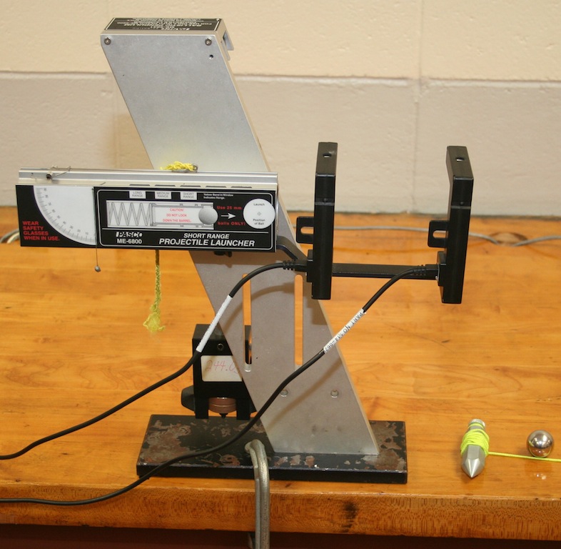
The apparatus displayed in the image below is used to launch the projectile (a 25mm steel ball). There are two photogates that will be used to establish the amount of time the projectile remains in each photogate, and the time it takes for the projectile to go from the first photogate to the second photogate. Using the times, the diameter of the ball, and the distance between the photogates, three independent ball velocities can be determined.
Note the clamp securing the launcher to the bench. It is critical that the launcher be secured to prevent errors resulting from the recoil of the launcher.
It is also critical that the photogates remain perpendicular to the bar supporting the photogates while determining the velocity of the ball. The thumb screws connecting the photogate to the support bar are not aligned with the actual photogate eyes; therefore if the photogate is allowed to turn slightly, the diameter of the ball will not pass through the eye of the photogate.
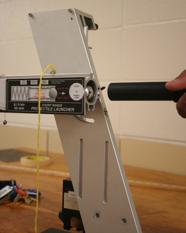
A close up of the launcher reveals a small plumb bob that indicates the angle of launch. The activity requires the projectile be launched horizontally.
The projectile is considered in flight the instant the ball looses contact with the spring. The ball position at this instant is indicated by the diagram near the front of the launcher's barrel labeled "Launch Position of Ball". This diagram should be used as a reference point for making measurements.
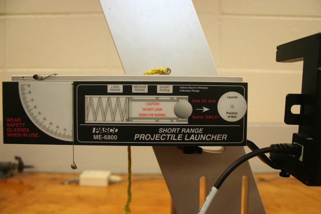
To load the launcher, first place the projectile (steel ball) in the barrel of the launcher. Then use the ram rod to push the ball to the desired range setting.
It is recommended that the "MEDIUM RANGE" setting be used for the entire experiment. It is critical that the same range setting be used for the entire experiment.
It is important that the ball be in contact with the spring prior to launching. If the ball rolls away from the spring after cocking, check the launch angle and adjust accordingly.
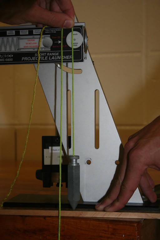
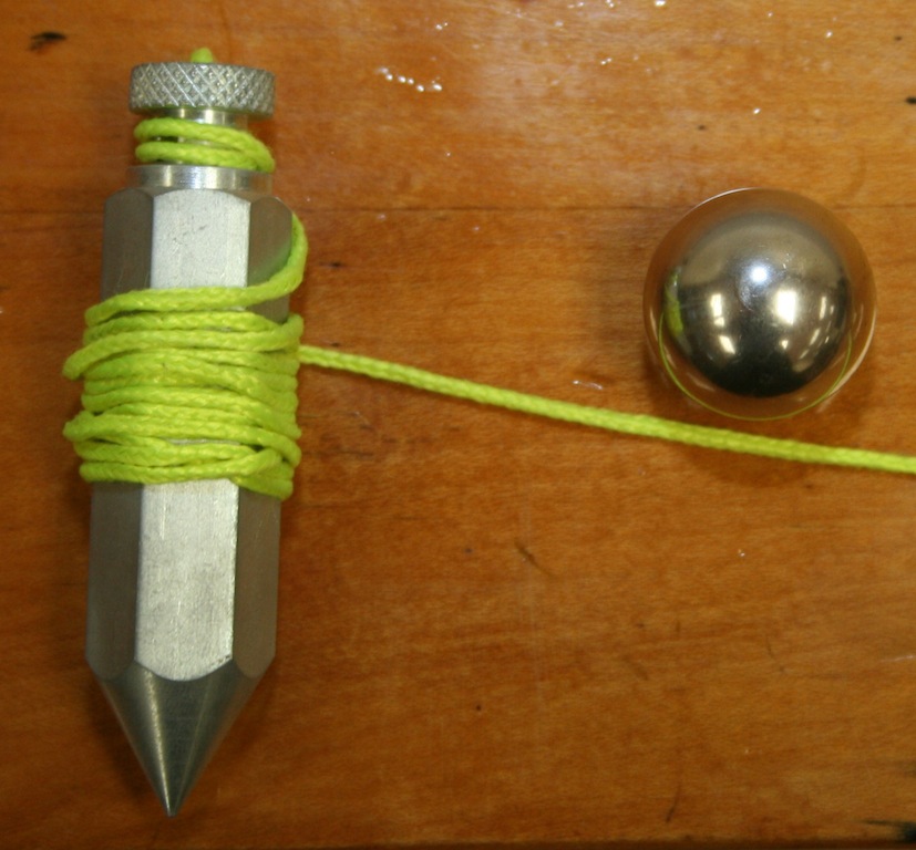
In addition to meter sticks, a plumb bob will be provided to aid in accurately determine the range of the projectile. It can also be used to aid in determining the position of the backstop that will hold the target.
This is just one example of how a plumb bob can be used to help in determining the range of the projectile. Using the plumb bob, the student on the right is aligning the zero end of a double meter stick with the marks on the floor that were made by the projectile. The student on the left is holding the double meter stick against the base of the launcher. Note that the plumb bob must be suspended slightly above the floor to allow it to swing freely in order to get accurate results. After the end of the double meter stick is aligned with the marks on the floor, the plumb bob can be used to determine the range as demonstrated in the next picture.
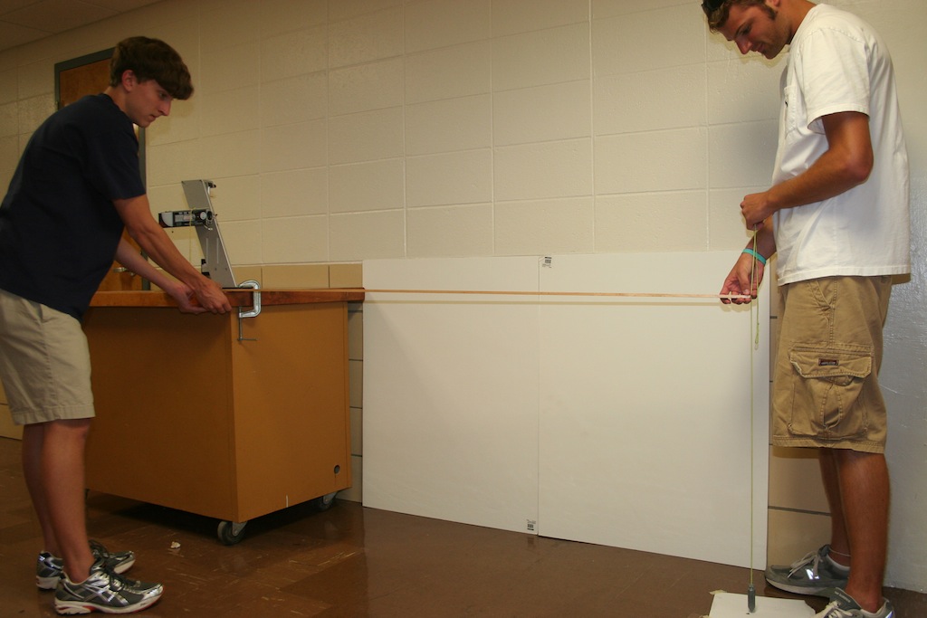
In this picture, students are attempting to use the plumb bob to transfer the launch position of the ball to the double meter stick being held against the base. Since the zero end of the double meter stick was previously aligned with the marks on the floor, the range will be indicated on the double meterstick by the plumb bob. Again the plumb bob must be suspended slightly above the meter stick to obtain accurate results.